🔬 Experimental Platforms
The experimental facilities provide acoustic material testing, complex sound-field characterization, and noise and vibration measurements. Six platforms cover acoustic material testing, multimodal acoustic sources and characterization, grazing-flow duct acoustics, fan acoustic mode characterization, underwater acoustic fields, and elastic wave fields, supported by general acoustic instrumentation.
1. Acoustic Material Testing Platform
The platform tests materials and structures under conventional, high-sound-pressure, multimodal, and high-temperature conditions. Different impedance tube systems provide measurements of sound absorption, acoustic impedance, transmission loss, and acoustic modes for the experimental evaluation of material and structural acoustic performance.
1.1 Conventional Impedance Tube System
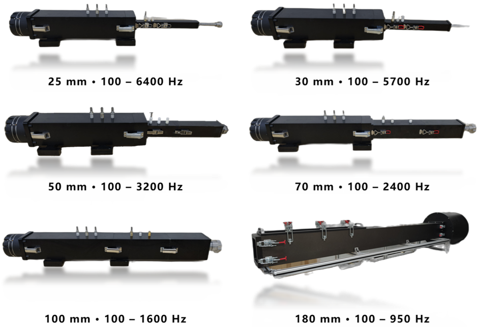
The system measures normal-incidence sound absorption, acoustic impedance, and transmission loss of materials and structures. Circular and square-section impedance tubes provide different sample sizes and operating bands, allowing an appropriate tube to be selected for measurements of sound absorption and transmission attenuation.
Functions
- Normal-incidence absorption characterization: measure the sound absorption coefficient and acoustic impedance of a sample to assess its absorption of normally incident sound and its acoustic boundary impedance.
- Transmission-loss testing: measure the attenuation of sound transmitted through a sample to evaluate material and structural sound insulation within the operating band of the selected tube.
Key Specifications
- Circular sections: 29 mm diameter (500–6400 Hz) and 100 mm diameter (50–1600 Hz).
- Square-section side lengths: 25, 30, 50, 70, 100, and 180 mm.
- Combined frequency coverage of the square-section tube series: 20–6400 Hz.
1.2 High-Intensity Impedance Tube System
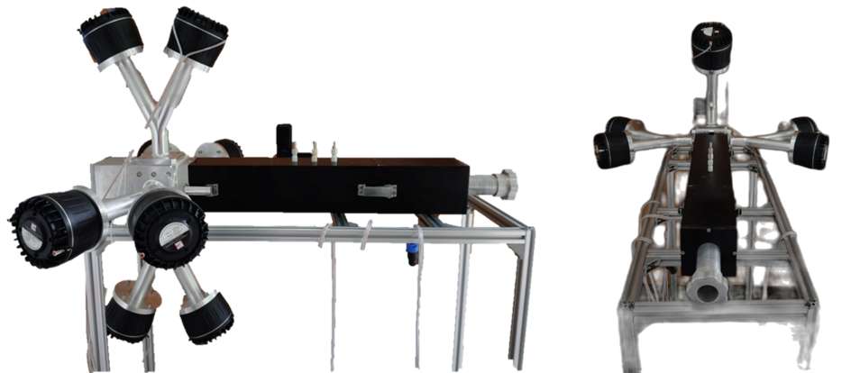
The system tests absorbing materials and acoustic liners under high sound pressure level excitation. Measurements at different excitation levels reveal changes in sound absorption and acoustic impedance, enabling characterization of sound-pressure-level dependence and nonlinear acoustic responses.
Functions
- High-sound-pressure absorption testing: measure sound absorption at different sound pressure levels to evaluate material and liner performance under intense acoustic excitation.
- Nonlinear impedance characterization: measure changes in acoustic impedance with sound pressure level to assess how excitation level affects the acoustic response of materials and liners.
Key Specifications
- Sound pressure level range: 100–150 dB.
- Operating frequency range: 400–6400 Hz.
1.3 Multimodal Impedance Tube System
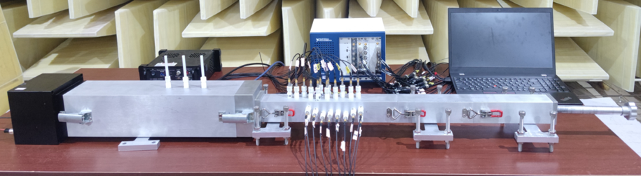
The system characterizes the multimodal acoustic performance of materials and structures in square waveguides. Multimicrophone pressure measurements support higher-order mode decomposition and the characterization of modal content and mode conversion during interaction with a sample. Modal tests are performed within the frequency bands in which the respective modes propagate.
Functions
- Higher-order acoustic mode decomposition: separate the propagating modes in the waveguide to characterize modal content and the response of individual modes.
- Mode-conversion characterization: measure changes in modal content before and after interaction with a material or structure to evaluate how the sample controls acoustic mode conversion.
Key Specifications
- Square waveguides: 25 mm × 25 mm (8 microphones) and 50 mm × 50 mm (32 microphones).
- Measurement frequency range: 50–12800 Hz; modal measurements are restricted to bands above the respective cutoff frequencies.
1.4 High-Temperature Impedance Tube System
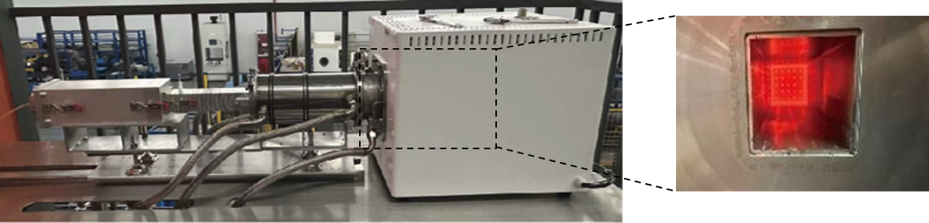
The system measures the sound absorption and acoustic impedance of materials and structures in heated gas. Acoustic measurements at different temperatures characterize temperature-dependent behavior and support the evaluation of absorbing materials and structures for high-temperature environments.
Functions
- High-temperature absorption characterization: measure sample sound absorption in heated gas to evaluate material and structural performance at elevated temperatures.
- Temperature-dependent impedance characterization: measure changes in acoustic impedance with temperature to assess its effect on the acoustic response of materials and structures.
Key Specifications
- Maximum test temperature: 1000 °C.
- Measurement frequency range: 50–6400 Hz.
- Sound pressure level range: 100–160 dB.
2. Multimodal Acoustic Source and Characterization Platform
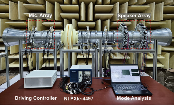
The platform generates and characterizes multimodal duct sound fields without flow. Amplitude and phase control of a multiloudspeaker source creates multimodal fields, while pressure measurements at multiple positions support azimuthal and radial mode decomposition. Measurements of mode conversion, transmission, and reflection characterize how materials and structures affect duct sound propagation.
Functions
- Multimodal sound-field generation: control amplitude and phase to generate multimodal sound fields in a duct without flow, providing controlled acoustic excitation for material and structural tests.
- Azimuthal and radial mode decomposition: use pressure measurements at multiple positions to determine duct modal content and characterize the propagation of different acoustic modes.
- Mode-conversion and scattering characterization: measure mode conversion, transmission, and reflection caused by materials or structures to evaluate their control of duct sound propagation.
Key Specifications
- Number of loudspeakers: 32.
- Excitable mode orders: azimuthal orders −4 to 4; radial orders up to 1.
- Operating frequency range: 100–3500 Hz.
- Number of measurement positions: 64.
3. Flow Duct Test System
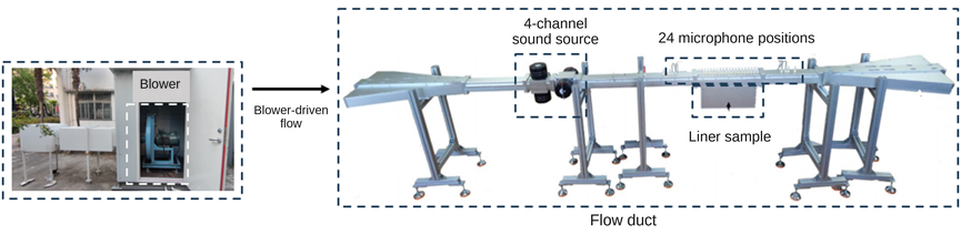
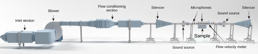
The system measures the acoustic performance of acoustic materials and liners under flow, high sound pressure level, and bias-flow conditions. It comprises an external blower, a rectangular test duct, a sound source, and an anechoic termination. Sound-pressure measurements at 24 microphone positions are combined with in-house data-processing software to obtain reflection, transmission, and sound absorption coefficients and acoustic impedance. The system also supports stable control of the target sound pressure level, flow velocity profile measurements, and flow resistance measurements.
Functions
- Grazing-incidence acoustic characterization: measure reflection, transmission, and sound absorption as sound propagates along the surface of a material or liner, extract acoustic impedance, and assess its ability to control sound propagation in ducts.
- High-intensity acoustic characterization: measure acoustic responses under excitation at different sound pressure levels, analyze changes in acoustic coefficients and impedance with excitation level, and investigate nonlinear effects in liners.
- Bias-flow acoustic characterization: measure acoustic properties when airflow passes through the perforations of a material or liner, and investigate the effects of bias flow on reflection, transmission, sound absorption, and acoustic impedance.
Key Specifications
- Duct cross-section: 51 mm × 51 mm.
- Flow velocity range: −84.1 to 84.1 m/s.
- Operating frequency range: 400–3,200 Hz.
- Number of microphone measurement positions: 24.
- Maximum sample dimensions: 400 mm (length) × 50 mm (width).
4. Fan Acoustic Mode Characterization Platform
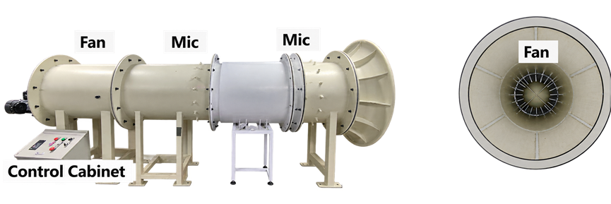
The platform measures duct noise and acoustic modes under fan operating and flow conditions. The single-stage fan system measures duct noise and liner insertion loss. The ducted-fan system measures transmission loss under flow and characterizes azimuthal and radial modes, supporting studies of fan-noise propagation and material-based noise reduction.
4.1 Single-Stage Fan Test System
The system measures duct noise during single-stage fan operation and evaluates acoustic liner noise reduction. The operating fan provides the test sound field, while duct acoustic measurements and liner insertion-loss tests characterize fan noise and its attenuation by the liner.
Functions
- Fan operating-noise testing: measure duct acoustic responses during fan operation to characterize the noise generated in the duct.
- Liner insertion-loss evaluation: compare duct noise with and without a liner under comparable fan operating conditions to quantify the liner’s attenuation of fan noise.
Key Specifications
- Duct diameter: 600 mm.
- Fan rotational speed range: −3000 to 3000 rpm.
- Acoustic measurement frequency range: 20–20000 Hz.
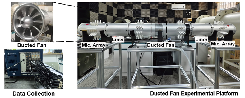
4.2 Ducted Fan Test System
The system measures the transmission loss of acoustic materials and liners under duct flow and characterizes azimuthal and radial modes in ducted-fan sound fields. Pressure measurements at multiple positions and acoustic mode decomposition are used to examine fan-noise propagation and the acoustic effects of materials and liners. Modal measurements are restricted to the propagating band of each mode.
Functions
- Transmission-loss testing under flow: measure the transmission loss of acoustic materials and liners in flowing ducts to evaluate their attenuation of transmitted sound.
- Azimuthal and radial mode characterization: decompose azimuthal and radial duct modes and measure the responses of propagating modes below 5000 Hz to analyze the modal content and propagation of fan noise.
Key Specifications
- Duct diameter: 150 mm.
- Modal decomposition capacity: 14 azimuthal and radial acoustic modes.
- Maximum flow speed: Mach 0.15.
- Fan rotational speed range: 11000–15000 rpm.
- Operating frequency range: 1000–5000 Hz.
- Number of measurement positions: 144.
5. Underwater Acoustic Field Characterization Platform
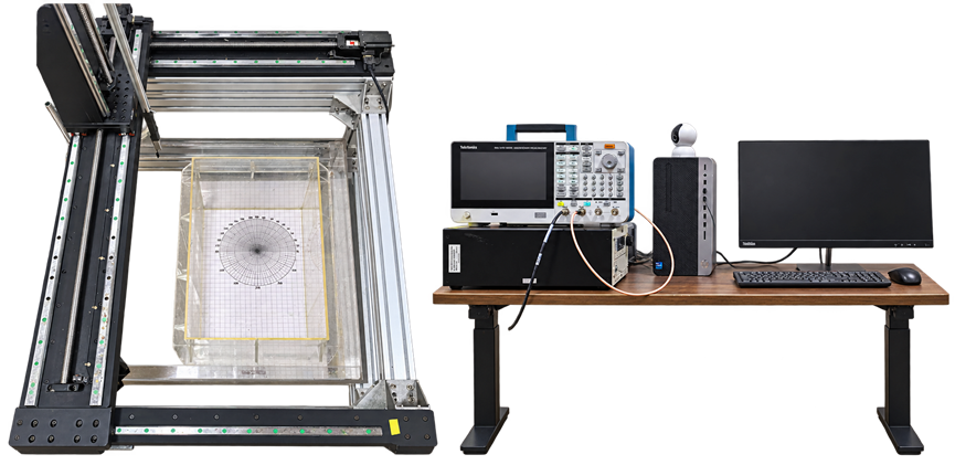
The platform experimentally characterizes spatial underwater sound fields and sound propagation. Underwater sound-field generation and spatial scanning measurements provide pressure amplitude and phase at different positions, revealing the spatial characteristics of transmitted, scattered, and radiated fields for underwater acoustic studies.
Functions
- Spatial underwater sound-field scanning: generate underwater sound fields and measure the spatial distributions of pressure amplitude and phase to characterize sound-field structure.
- Sound-propagation and scattering characterization: use spatial pressure measurements to investigate underwater transmission, scattering, and radiation and the associated changes in the sound field.
Key Specifications
- Scanning range: 1 m × 1 m × 0.6 m.
- Measurement frequency range: 100 kHz–20 MHz.
6. Elastic Wave Field Characterization Platform
The platform experimentally characterizes structural vibration and elastic-wave propagation. Scanning laser vibrometry provides non-contact velocity measurements, while piezoelectric sensor arrays provide contact acceleration measurements. The complementary methods characterize structural modes and elastic-wave propagation through local responses and spatial distributions.
6.1 Scanning Laser Doppler Vibrometry System
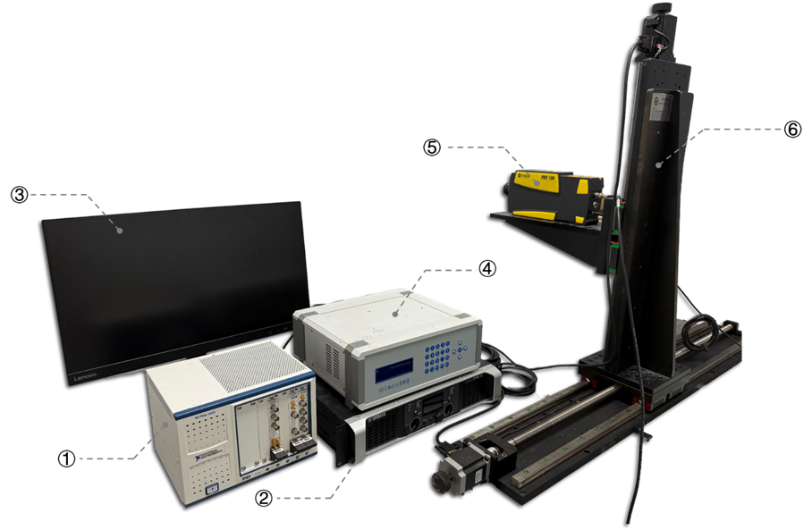
The system provides non-contact measurements of structural surface vibration velocity and its spatial distribution. It measures the surface velocity component along the laser measurement direction and uses two-axis scanning to acquire vibration responses at different locations for structural modal and elastic-wave propagation experiments.
Functions
- Non-contact vibration-velocity measurement: acquire the surface velocity response along the laser measurement direction to characterize vibration at the measurement position.
- Two-dimensional vibration-field scanning: measure vibration responses at different surface locations to analyze structural modes and the spatial propagation of elastic waves.
Key Specifications
- Vibrometer frequency range: 0.5 Hz–22 kHz.
- Two-axis scanning travel: approximately 1200 mm × 500 mm.
6.2 Piezoelectric Sensor Array Test System
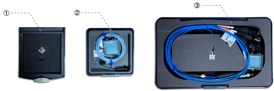
The system provides contact measurements of structural vibration acceleration. Single-axis and triaxial piezoelectric accelerometers characterize responses at individual or multiple positions, supplying acceleration data for structural modal analysis and elastic-wave propagation experiments.
Functions
- Single-point and multipoint vibration measurement: acquire acceleration responses at different structural locations to characterize spatial differences in vibration.
- Single-axis and triaxial response characterization: measure acceleration in a selected direction or along three axes as required for structural modal and elastic-wave propagation studies.
Key Specifications
- Sensor inventory: 15 single-axis and 7 triaxial accelerometers.
- Single-axis sensor frequency ranges: 0.3 Hz–6 kHz or 1 Hz–8 kHz, depending on the selected sensor.
- Triaxial sensor frequency range: 1 Hz–13 kHz.
7. General Acoustic Instrumentation
The instruments provide sound-field excitation, acoustic parameter measurements, and dynamic signal acquisition for the test platforms. The acoustic analyzer, omnidirectional source and power amplifier, and multichannel acquisition and signal-generation equipment support acoustic-environment, room and building acoustics, and vibroacoustic experiments.
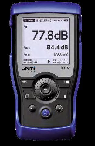
7.1 Audio and Acoustic Analyzer (Left)
The analyzer measures acoustic environments and room-acoustic parameters. Sound-level, spectral, and reverberation-time functions, together with different frequency weightings and spectral analysis methods, characterize sound levels, frequency content, and reverberation.
Functions
- Sound-level measurement: apply the appropriate frequency weighting to measure sound levels for acoustic-environment assessments.
- Spectral analysis: use octave-band, one-third-octave-band, and FFT analysis to characterize signal frequency content and identify dominant frequency bands.
- Reverberation-time measurement: measure room reverberation time to characterize acoustic energy decay and room reverberation.
Key Specifications
- Frequency weightings: A, C, and Z.
- Spectral analysis: octave bands, one-third-octave bands, and FFT.
- Reverberation-time measurements: octave bands from 63 Hz to 8 kHz.
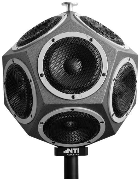
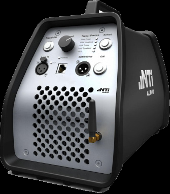
7.2 Omnidirectional Sound Source and Power Amplifier (Center Two Images)
The omnidirectional source and power amplifier provide acoustic excitation for room and building acoustics tests. They work together to establish the test sound fields required for reverberation-time and airborne sound-insulation measurements.
Functions
- Room-acoustic test excitation: establish sound fields for reverberation-time and related room-acoustic measurements.
- Building sound-insulation test excitation: provide source excitation for airborne sound-insulation measurements in conjunction with acoustic measurement instruments.
Key Specifications
- Number of loudspeakers: 12.
- Equalized source frequency range: 100 Hz–8 kHz.
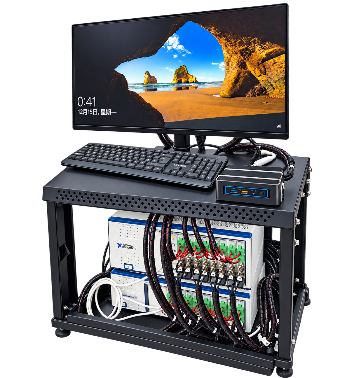
7.3 Multichannel Data Acquisition and Signal Generation (Right)
The equipment provides signal output, dynamic response acquisition, and digitized recording for acoustic and vibration experiments. Signal generation and multichannel acquisition support the test platforms, together with experimental control, signal processing, and data analysis.
Functions
- Test-signal output: generate excitation signals for sound sources and acoustic or vibration experiments.
- Dynamic response acquisition: acquire and digitize multichannel dynamic responses to provide experimental data for acoustic and vibration analysis.
- Experimental control and data processing: support test control, multichannel signal processing, and measurement-data analysis.